

Atari 2600 Hardware Design: Making Something out of (Almost) Nothing
Atari Combat, 1977
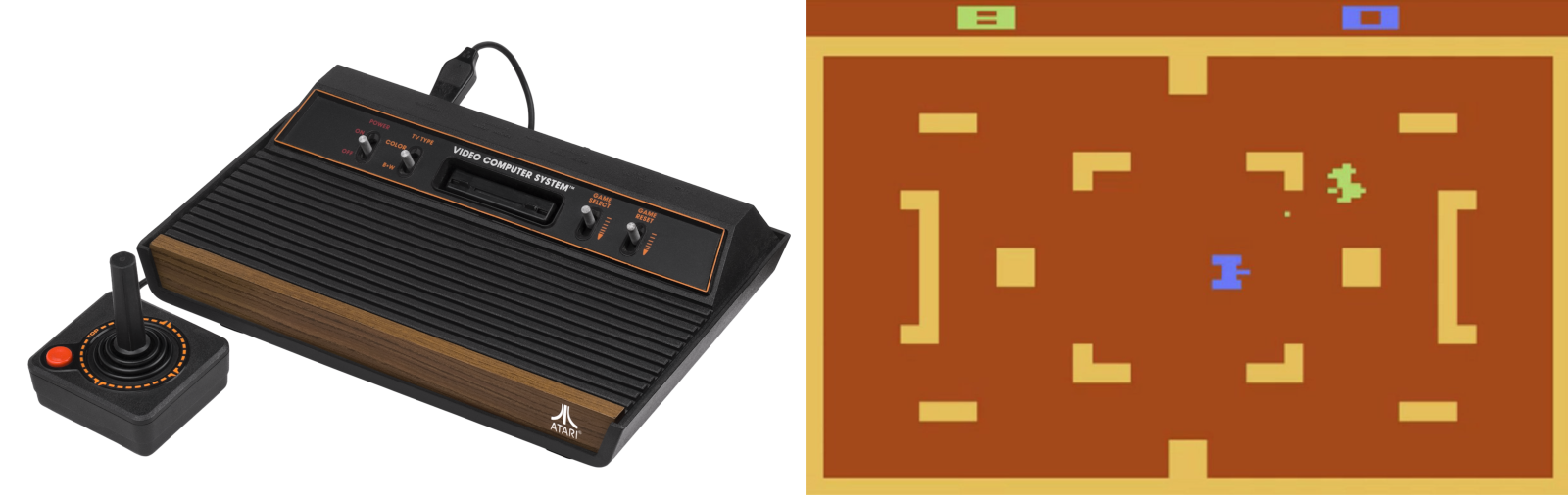
The Atari 2600 wasn’t the first home video game console with replaceable games, but it was the first to be widely successful. Introduced in 1977 as the Atari VCS (Video Computer System), and later renamed Atari 2600 in 1982, it eventually sold over 30 million units and established a new market that still endures today in the PlayStation and Xbox. Prior to the 2600, most video game systems were either coin-operated machines found in bars, or fixed-function devices limited to a few built-in games like Pong. Atari’s first home system was the beginning of a new age.
This wood-grained block of electronics preoccupied my young mind. I wanted one badly, but never succeeded at convincing my parents. I was eleven years old in 1982 when my friend Fred got an Atari, and I was sick with jealousy:
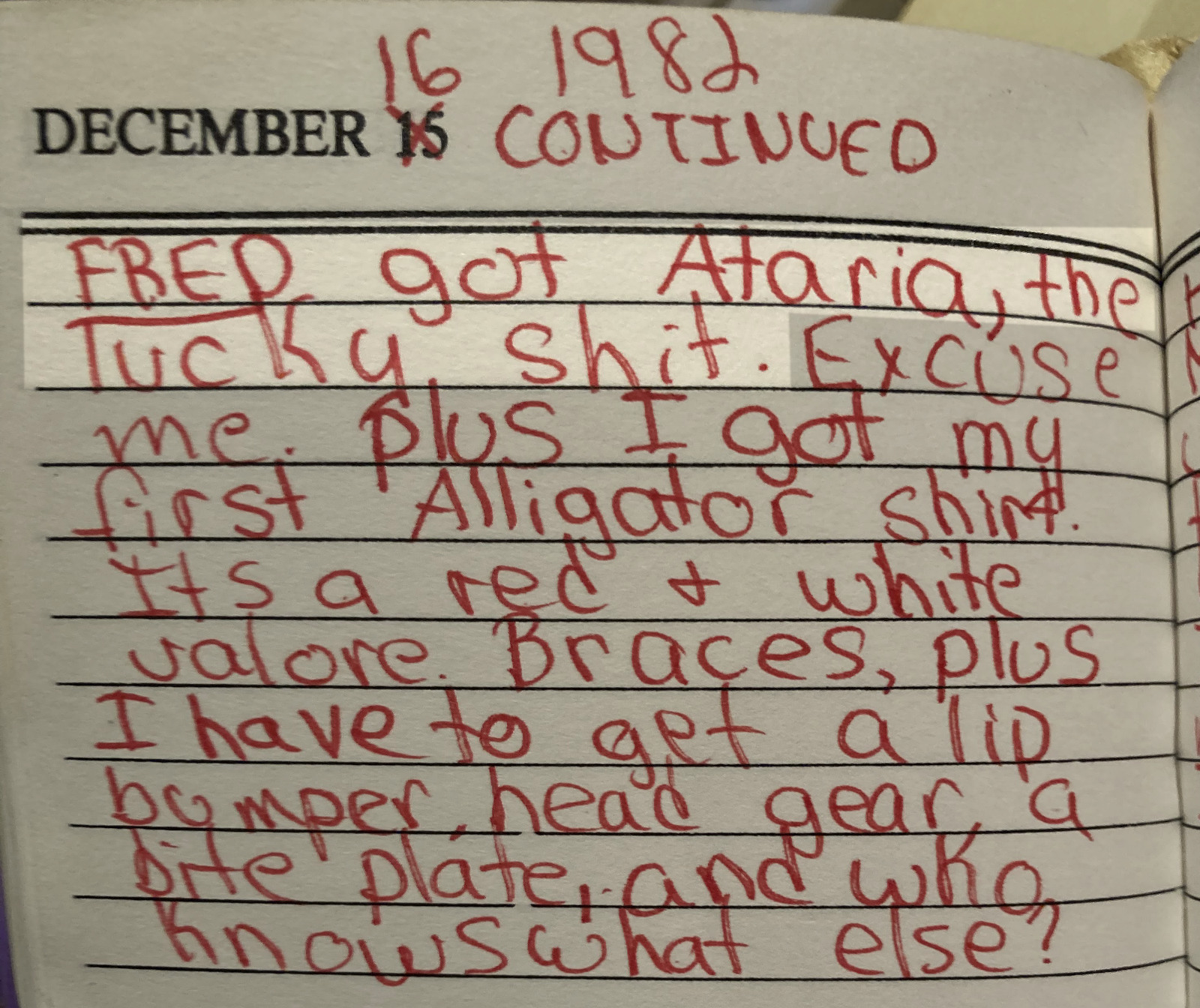
December 16 1982, arrival of Ataria (sic)
What a day! Not only did Fred get an Atari system, but I got braces and an Izod Lacoste alligator shirt.
Atari 2600 Hardware Overview
Recently over the holiday break, I became interested in the 2600’s hardware architecture and started reading everything that I could find about it. I knew that it was some kind of 6502-based system, and I’d heard mentions of “racing the beam”, but that’s as far as my knowledge went. I was shocked to discover how primitive the 2600 hardware was, even compared to contemporary 6502 systems like the Apple II, Commodore PET, and even Atari’s own 8-bit computers.
Inside that wood-grained box there were only three digital chips:
- 6507 CPU (pin-reduced version of the 6502)
- 6532 RIOT
- TIA (Atari custom IC)
Notably absent from this list was any RAM or ROM! The ROM came from whatever game cartridge was inserted – there was absolutely no built-in I/O helper routines or operating system, so it was up to the game programmer to provide everything. Game cartridges were limited to 4 KB and many early games were only 2 KB. Any of the photos on this page are vastly bigger than that.
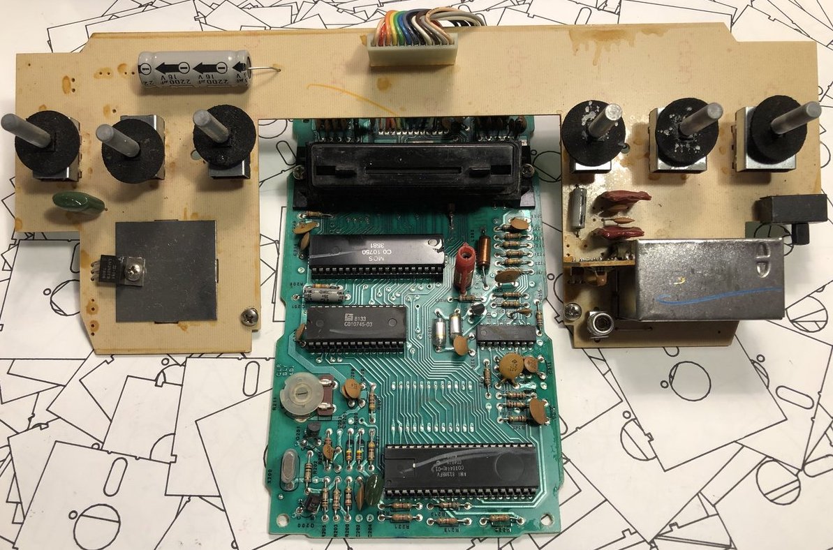
early version of Atari VCS circuit board
RAM was limited to the tiny amount of storage space built-into the 6532 RIOT chip – just 128 bytes. 128 bytes! That is… I don’t even… that is small. Like really, really small. I might have guessed 1 KB or 2 KB RAM, but 128 bytes is just in another category entirely. What’s worse, this tiny amount of RAM had to serve as both the scratchpad/heap and as the stack! Programmers got a few bytes for things like player and item locations, strength, score, and that’s all.
But hold on, because it was even worse than you think. This pin-reduced 6507 eliminated the 6502’s NMI and IRQ pins, so there was no hardware interrupt capability at all. Everything had to be accomplished with software timing and polling. For a real-time system built around the concept of racing the beam, this was just masochism.
And for the final kick in the nuts, there was no framebuffer. There wasn’t even a line buffer. The programmer only had a few TIA registers to play with and nothing more. Most graphics had to be generated by the CPU on the fly, at the very moment that the television’s electron beam was scanning past the pixels of interest. Even the VSYNC signal for the television had to be handled in software. With hardware like this, I’m surprised the Atari 2600 didn’t require a coal-fired steam engine or a wooden crank handle to boot the games! It’s crazy. I love it.
Inside the TIA Chip
The heart of the 2600 is Atari’s custom-designed TIA chip – the Television Interface Adapter. You can find the hand-drawn TIA schematics on the web if you’re curious how it works. The TIA internals look very strange to modern eyes, beginning with the extensive use of linear feedback shift registers where you would expect to find binary counters, for things like the horizontal sync counter or the sprite position registers. I’ve seen LFSRs used as random number generators in other 8-bit designs, but never as a general-purpose counter. These LFSRs also use two separate clocks, 180 degrees out of phase, which seems equally strange. Here’s the six bit horizontal sync counter:
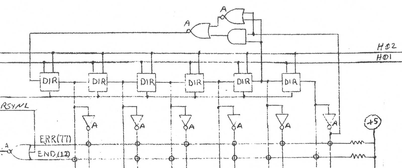
The chip designers must have had their reasons: maybe LFSRs were cheaper to implement or required fewer transistors than regular binary counters? If you just need a six bit counter, then ultimately it doesn’t really matter if it counts 64 states from 000000 sequentially up to 111111, or if it follows some other random-looking but deterministic sequence of states. Either way you can add logic to check for the terminal state and reset the counter when needed. If anyone has an idea why the TIA’s designers used LFSRs for this stuff, I’d love to hear about it. Fortunately the Atari 2600 programmer is mostly insulated from this LFSR funny business.
So how do games actually draw stuff? The simplest place to begin is with what Atari calls the playfield, and is effectively a background pattern on the screen. The TIA has 20 bits of register state which the programmer can modify, and which is used to create a one-dimensional low-resolution monochrome bitmap on the left half of the scan line. The right half of the line is either a copy of the left, or a mirrored copy. Want something completely different on the right side? Too bad. Want multiple colors? Too bad. The same 20 bits of playfield register state are used on every horizontal scan line, too. Want to display something different on each line? That requires constantly modifying the playfield registers, before each new scan line is drawn. There are only 76 CPU clock cycles during each scan line, and with most CPU instructions requiring 2 to 5 clock cycles, that doesn’t leave much time to do… basically anything.
This playfield behavior explains why so many Atari games have left-right symmetry in their backgrounds, walls, or similar content. Look at this image of Pitfall, and notice how the tree canopy, tree trunks, ground, pit, and underground cave all show left-right symmetry. These are all built from the playfield (plus additional tricks to be described later). The only sprites are Pitfall Harry, the vine he’s swinging from, the rolling log, and the scorpion.
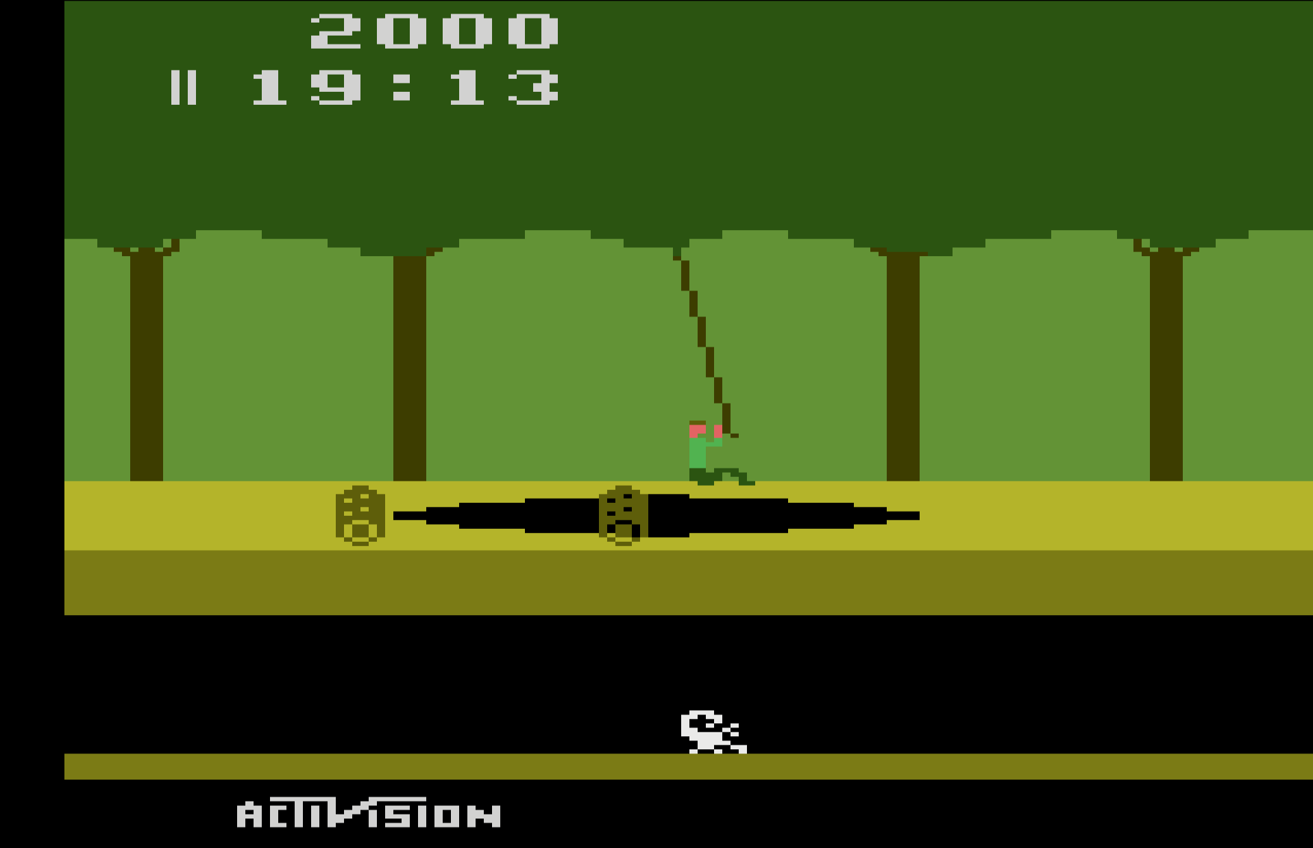
What about those sprites? Atari called them players and missiles, but the concept is the same. Players are sprites eight bits wide, and the pixels are smaller than playfield pixels. They can be positioned anywhere on the scan line, but like the playfield, they’re one-dimensional monochrome bitmaps. If the programmer wants 2D sprites (which they certainly do), then the code must constantly modify the player graphics register, updating it before each new scan line is drawn, including setting the register to zero for the areas above and below the player sprite where nothing should be drawn. Does that sound incredibly tedious? You bet!
Missiles are only one bit wide instead of eight, but are otherwise identical to players. The TIA provides two players, two missiles, and a ball that’s like a third missile. If the programmer wants more sprites than this, or wants multi-colored sprites, or anything else that the hardware doesn’t provide, then they’ll need to get fancy by combining multiple players and missiles, or else make lots of precisely-timed updates to the TIA registers to create the illusion of additional sprites and colors.
One common technique was to design games with distinct horizontal bands of activity, like Pitfall here. That allowed the same player sprite to be reused multiple times as the screen was painted from top to bottom. For Pitfall, player 0 might first be used to draw a score digit at the top of the screen. Then the same player 0 hardware resource would be used to draw part of Pitfall Harry, then to draw the rolling log, and finally to draw the scorpion. Since none of these overlapped each other horizontally, there was no conflict as long as the software could update the player graphics and position quickly between scan lines.
Atari Hardware Tricks
Under a one-dimensional hardware system like this one, collision detection would have been extremely difficult if it were left up to the software to provide. The necessary degree of bookkeeping would be too much: checking all the sprites and the playfield for collisions with each other would be virtually impossible with only 76 clock cycles per scan line, on top of all the CPU’s other critical tasks. Fortunately the TIA provides the very cool feature of hardware collision detection, at the pixel level! Any time a non-zero pixel overlaps another non-zero pixel of the playfield, a player, a missile, or the ball, a corresponding collision bit is set in the TIA, which software can later check and clear. With a total of six graphics objects there are (6*5)/2 = 15 possible collisions (an application of the Handshake Problem) to be tracked by the TIA. Nice!
Horizontal positioning of players and missiles is notoriously difficult. Most programmers would expect that the TIA has registers to specify the horizontal position of each sprite, but no. That would be too easy. On the Atari 2600, the horizontal position of a player or missile is set by writing to a special TIA register at the exact moment the electron beam passes the desired position. Think about that for a minute. The specific value that’s written to the register doesn’t matter. The program isn’t telling the TIA “put player 0 at position X”, it’s telling the TIA “put player 0 at… (wait for it) RIGHT HERE!” Thanks to this design, horizontal positioning requires synchronizing a software loop to the start of a scan line, delaying some amount of time dependent on the desired horizontal position, and then writing to the TIA register. Rather than setting a specific value for the horizontal position, the software is actually resetting one of those LFSRs in the TIA.
With the standard technique for this timing-based horizontal positioning, it’s only possible to get a horizontal resolution of five CPU clock cycles, which is equivalent to 15 pixels. To help the programmer get fine-grained control, the TIA provides additional registers that enable each sprite to be adjusted between -8 to +7 pixels from its ordinary position. It’s clumsy, but the combination of timing-based positioning plus fine-grained adjustments enable sprites to be positioned at any horizontal coordinate.
The fine-grained horizontal control involves writing to a TIA register named HMOVE, and its use leads to one of the Atari 2600’s most notorious graphical flaws: an irregular series of black lines on the left side of the screen, obscuring part of the playfield. This is often called the HMOVE comb. Here’s an example from Space Invaders:
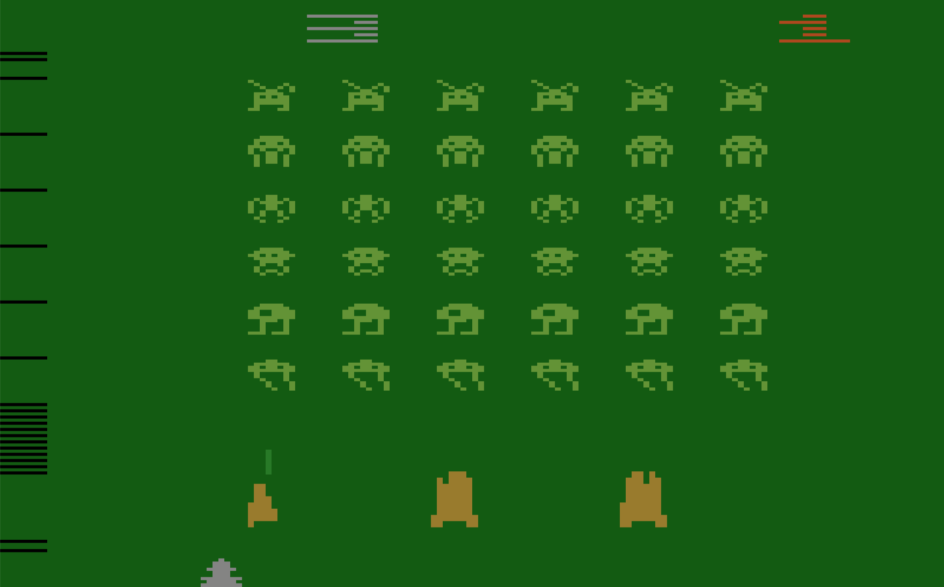
This is a side-effect of the way the TIA performs fine-grained adjustment of sprite positions, and many games exhibit this problem. Any time HMOVE is written to during a scan line, the horizontal blanking interval will be extended by eight pixels on that line, cutting off the left edge of the line. Is it a bug? An unintended feature? The exact details are much too complex to describe here, but Andrew Towers has written a very thorough explanation of TIA behavior which you’ll find at http://www.atarihq.com/danb/files/TIA_HW_Notes.txt. See the heading Playing with the HMOVE Registers.
Why do only some games display this HMOVE comb effect, and others apparently don’t? It only appears when games reuse the same sprite at different vertical positions on the screen, which requires adjusting the sprite’s horizontal position mid-frame. Space Invaders does this extensively, but simple games like Combat don’t do this. Combat is limited to the two built-in players and two built-in missiles, with no mid-frame repositioning, and therefore no HMOVE comb.
Pitfall takes a different approach, with a solid black bar at the left edge of the screen instead of a comb. This is the result of writing to HMOVE on every scan line, even when it’s not needed. Activision used this technique in many games, apparently having concluded that a solid black bar looked nicer than a partial black comb.
There are many more software tricks necessary for creating a high-quality Atari game. A non-symmetrical playfield or multi-colored playfield can be created by modifying the playfield graphics and color registers at precisely the right times, but it’s not easy! Color registers can also be modified between lines, to provide more total colors on the screen even when the number of colors on a single line is limited. Sprites can be reused and repositioned at different vertical positions, or can even be reused at the same vertical position with careful timing and attention to TIA behavior. Atari 2600 programming is a very deep topic, and it’s a long journey from bouncing ball demos to a high-quality game like Pitfall.
Atari 2600 Development Today
Want to try your hand at writing some Atari game demos? Yes you do, and it’s much easier today than it was in 1977. Start with this Atari 2600 Programming for Newbies tutorial written by Andrew Davies. Software is written in 6502 assembly language, and if you’re reading this blog, then there’s a good chance you already know it. To assemble your software, use DASM, a venerable and feature-filled cross-platform assembler for the 6502 and other 8-bit CPUs. If you’ve got a real Atari 2600 console, you can write your assembled program’s binary image to an EPROM and make your own game cartridge. If that sounds like too much bother, try the Z26 or Stella software emulators.
Did I butcher some technical explanation here, or omit important details? Please let me know! I’m just a beginner on this Atari hardware journey, with much still to learn. Look for my first 2600 game, coming soon?
Read 31 comments and join the conversation31 Comments so far
Leave a reply. For customer support issues, please use the Customer Support link instead of writing comments.
I had a 2600 as a kid, and have happy memories of hours spent playing Adventure and Tank and Space Invaders. Even then, we kinda knew the games were not great, but it was better than feeding quarters into an arcade machine (and arcades were kinda scary to a young kid).
Later, I cut my teeth on programming the Atari 400/800 generation of computers. They felt a little limited in terms of memory, and the tricks to squeeze more graphics performance were pretty hackish. Now hearing how extreme the 2600 was though, I realize that we had it easy!
Great write-up and very accurate. Those Pitfall sprites are doing even more work. They also form the small branches of the trees. And drawing that score is an incredible feat of code acrobatics.
I’d like to suggest to adventurous readers https://8bitworkshop.com/ write and run Atari 2600 code directly in your browser. It also features some useful examples to learn from.
Very good blog post! The Atari’s got a soft spot with me. It really was meant to sell you a Tank game and a Pong game. It’s amazing they got anything else working on it. Pitfall II remains one of my favorite games of all time, especially for that music.
Two things I’d wanna add, not because they’re missing I’d say (you were focused on the raw specs of the hardware), but because anyone who wants to write a 2600 game would be good to know:
1) Most Atari games these days (and even back then) extend what the system can do in the cartridge. Much larger ROMs can be used through bankswitching, and cartridges can also add their own RAM space to massively enhance what the system can do. There was also an add-on called the Supercharger (from a company called Starpath) that allowed loading of games from cassettes and gave any games running from it 6KB of extra RAM. The Supercharger is best remembered for having an “official” version of Frogger for it, and the graphics on that one are stunning.
2) For anyone who loves learning about the limitations of how these games work, please go read Racing the Beam. It’s an MIT Platform Studies (which explore the limits and strengths of a variety of game consoles and media devices, the Wii and the Kindle come to mind) book about the Atari and it is filled with fantastic anecdotes about how anyone got anything done with that box back then. My favorite story in the entire book was when David Crane gave River Raid programmer Carol Shaw out loud the exact assembly code to make a klaxon sound for when the player was about to run out of fuel. The people who knew the Atari knew it REALLY well.
On the LFSRs: yes, they were both smaller and faster.
A counter needs storage and logic for each bit. There’s a trade-off between size and speed, but neither is good. A shift register needs two inverters and two pass transistors. They’re as small and fast as you can get.
Ken Shirriff unsurprisingly has a good explanation of NMOS dynamic shift registers at https://www.righto.com/2022/04/inside-apple-1s-shift-register-memory.html All you need to turn that into a counter is a single XOR gate on the input.
Wow, 8bitworkshop.com is extremely impressive! It’s an editor, assembler, 2600 emulator, and debugger all rolled into one, and hosted in your browser so there’s nothing to install or configure. It includes several dozen well-documented example demos. And beyond the 2600, it also supports many other retro hardware platforms, as well as a Verilog IDE for building games directly from hardware gates. What more could anyone possibly want? Thank you Steven Hugg.
I am confused by this bit: “Since none of these overlapped each other horizontally, there was no conflict as long as the software could update the player graphics and position quickly between scan lines” — is it possible that you meant “none of these overlapped each other *vertically*”?
I had wondered about the cause of those black lines at the left edge of the screen, but had not ever looked into it. So I’m glad to learn the term “HMOVE comb”.
I think the the phrase “horizontal overlap” could be clearer. I meant that a horizontal line extended from one sprite would overlap another sprite. The point is that it’s difficult to reuse a sprite multiple times on the same scan line, but it’s relatively easier to reuse a sprite on a different scan line. As long as your game characters are all constrained to separate horizontal bands on the screen, then they can all be constructed from a single sprite by modifying the sprite registers between scan lines.
Join the atari 2600 demoscene! And don’t listen to what anyone says, it’s a lot more fun if you can cram your demo into a 4k ROM:
https://www.youtube.com/watch?v=mkhxwmzLfV0
Though I have to admit the Myst port takes a 16k ROM
Is it so surprising that a LFSR is simpler to implement than a binary counter?
For an n-bit LFSR, you really only need n registers and an xor, usually of 2 or 3 inputs.
For an n-bit binary counter, you need n registers and n – 1 half adders. If the counter gets long enough, you’ll get a critical carry path that you need to deal with somehow.
“For an n-bit binary counter, you need n registers and n – 1 half adders.”
Nope, just n flip-flops.
For a “running light” output that always has 1 of 2^n bits set (or cleared), you additionally need an n bit decoder, basically just an n input AND gate for each of the 2^n outputs. Because the flip-flops provide both an inverted and a non-inverted output, you do not need any extra gates. Instead of the AND gate, you can also use a NOR gate and use the flip-flop outputs with the inverted polarity.
How is everybody connecting their modern TVs and PC monitors to Atari 2600 systems today? It looks like some people keep an old-school CRT just for this purpose, but I’d prefer to avoid that. The Atari console only provides RF out, which is mostly useless today. Modify the console to provide composite video and separate audio outputs? Use a frame scaler? What about lag introduced by upscalers and digital video processors?
I wrote 2600 games for Atari (Submarine Commander and Double Dunk) and Activision (Dolphin). It was a terrific challenge.
I modded my 2600 for composite output. It’s a relatively small mod, but it’s a bit of a pain to do especially if you’re trying not to leave the machine as stock as possible. Desoldering the RF shield was a pain, and in the end I had to clip a transistor off which pained me a bit. In the end it gives decent video assuming you have a TV/monitor that can display composite OK.
@Matthew Hubbard that’s very cool! What were the development tools like at Atari and Activision? Did you have any method for debugging on the running hardware?
@deater the composite mod might be the best solution. I’ve found a few designs for the mod, and they’re all slightly different. I would love to see some explanation of exactly how they work, how the specific component values were chosen, and why some of the original components need to be removed. If you want to keep the Atari console stock, there’s also the option of an RF demodulator like http://www.ambery.com/rfdm2.html . I would suspect the quality is worse from an RF demodulator, compared to keeping the audio and video separated from the beginning. But RFDM2 appears to do a nice job in the reviews that I’ve seen.
For what it’s worth, Tim Worthington’s 2600RGB ( https://etim.net.au/2600rgb/ ) appears to be the current best-available video modification. It does composite, s-video, and RGB. I put one in my 2800 after being very dissatisfied with the UAV; the video output is very stable and clean.
Thanks for that 2600RGB pointer! It’s interesting how some people are happy playing on a software emulator, some want the original hardware, and some enjoy a new-old-style hardware solution like the Retron 77. I normally prefer the original hardware. The standard composite video mod is a simple hack and IMHO it’s within the spirit of “original hardware”, while solutions like the 2600RGB might be too big a step towards hardware emulation for me. In this case, it bypasses the TIA chip and replaces it with a new SoC module that has substantially more computing power than the whole Atari console. But it should do a great job with video using that approach.
How to connect Atari 7600 to today’s TV?
i think you need an very old working analog
glass TV with round – “antenna” input 😉
me again – found some “VHS” to – SCART adapters on electronic bay
maybe some of this or to HDMI converter use VHS to modern TV
If your TV has a coaxial cable TV input, you can hook the Atari RF output to that, but you’ll need a simple adapter between the unthreaded and threaded connectors. https://www.ebay.com/itm/203793056438
Great read.
If anyone wants a very well explained introduction to 6502 assembly for the Atari VCS, pikuma is definitely a must. I took Gustavo’s course on Atari 2600 programming and I can’t recommend it enough.
Atari 2600 Programming:
https://pikuma.com/courses/learn-assembly-language-programming-atari-2600-games
A shift register which can hold its state indefinitely would be larger per bit than a counter which can do likewise, but a dynamic shift register contains four transistors and two passive pullups per bit. A shift register stage is basically an inverter (a transistor to ground with a passive pullup on the output) with a pass transistor on the input. When the gate of the pass transistor is high, the gate of the output transistor will be connected to the input. When the gate of the pass transistor is low, the gate of the output transistor will stay at whatever voltage it’s at until leakage pulls it high or low, which will hopefully take a few microseconds. Note that dynamic logic is an essential design aspect of not only in the TIA, but also in the 6502/6507, which must be clocked at least once every ten microseconds.
I don’t think I’d agree with the statement that “most” cartridges contain enhancements. Back in the day, most of the smaller cartridge manufacturers didn’t want to make custom parts; using stock parts, a 4K cartridge would require a stock PROM and an inverter, while the smallest common design for a bank-switched cart required two additional chips. In fact, it is possible to use a single stock 1970s-era chip to implement a bank-switched cartridge, but I don’t think anyone did so prior to the “0840” board design used in my Toyshop Trouble game.
BTW, have you seen Toyshop Trouble and Stella’s Stocking? The latter gets a really tiny bit of help from the programmable logic device on the cartridge, which is set up to allow code to access two different 4K banks on each scan line without wasting any cycles on bank switching, but the BTP-II music player does all the work of generating 4-voice audio in software using 46 cycles of every 76-cycle scan line, without need of a DPC (David Patrick Crane) chip.
I tried Toyshop Trouble in an emulator, and it’s a lot of fun! Very nice work! Looks like Stella’s Stocking isn’t available for emulators but I watched a demo video that included the audio player.
I’m finding 2600 programming to be very interesting, but difficult! I like searching for ways to optimize every last cycle in a piece of code. That’s usually not necessary for 8-bit Apple programming, but for the 2600 every clock cycle is precious and can be the difference between a game working or not working. I also get a kick out of using the illegal 6502 opcodes to shave a few extra clock cycles here and there. I never had a chance to try those for Apple development since those opcodes don’t work on the 65C02, but only on the earlier NMOS 6502.
I’m currently following the Let’s Make a Game! (Collect) tutorial for Atari newbies, and pausing periodically to experiment with code to make interesting graphical patterns.
It seems that the ultimate in clock cycle optimization would be to use self-modifying code, with key kernel sections located in RAM. There’s not much RAM to work with though!
Toyshop Trouble may have some problems with the vsync timing or rate. In the Stella emulator, if you turn on Developer->Video->Developer Settings (which sets the sensitivity and recovery to 8 and 2 respectively), then the Toyshop Trouble screen image rolls continuously. But with the standard emulator settings (less sensitivity to timing glitches) the screen image is OK.
It’s been many years since I’ve looked at it, but I’m pretty sure I had the vertical timing rock solid on Toyshop Trouble. I know that the Stella’s Stocking title screen runs at 264 lines instead of 262, because the music player logic needs to process the “cleanup” for each of the four voices in strict rotation, one per scan line, to achieve glitch-free audio, but monitors don’t care so long as the rate is consistent.
Self-modifying code is actually a fair bit short of achieving the ultimate clock cycle savings; I’ve actually gone three steps beyond:
1. Bank-switching operations that set things up based upon the address being read. I have some bitmap graphics demos that plot a pixel at address X,Y using LDA $7F00,X / ORA $1E00,Y / STA $1E00,Y.
2. On some ARM-based cartridges like Fred Quimby’s Harmony/Melody carts, the ARM can generate immediate-mode 6502 instructions in real time.
3. A technique I wouldn’t use except that an unreleased expansion for the 2600 did so: have the 6502 store $FF to TIA addresses at the same time as the cartridge grounds any data-bus bits that should be zero. I’ve done this, and it allows really insane numbers of shapes to be drawn on screen at once–two groups of eight sprites with “flicker-blinds”, all with independent color and shape.
Incidentally, I found some of the NMOS 6502’s “undefined-at-the-time” very useful when doing Toyshop Trouble, and wish some of them had been recognized by the designers of the CMOS version. While some CMOS-only instructions fill in gaps in the 6502 design, many of them seem less useful than some “undefined-at-the-time” instructions in the NMOS version.
Good 65C02 instructions: PHX, PHY, PLX, PLY, STZ, and (zp) addressing mode
Good NMOS-only instructions I wish 65C02 had: LAX, SAX, DCP, and sorta SBX.
SBX is a weird instruction on the 6502. It ANDs the value of A and X, subtracts an immediate value from that, treating carry the way SBC does, and then stores the result to both A and X. This combination of actions is less useful than some simpler instructions would be, but supports two useful patterns:
LDA #255
SBC #nn
will behave in a manner consistent with:
TXA
SEC
SBC #nn
TAX
but one byte shorter and four cycles faster. Having a subtract-from-X which ignored A would be nicer, but even having to trash A the instruction can still be useful. The other nice usage case is:
LDA mask [or LDA #mask]
SBX #0
as an alternative to:
TXA
AND mask
TAX
which is the same length, but two cycles faster.
Hardware update: I’m now the proud owner of an Atari 2600 Jr, and it mostly works! I’ve cleared the first board of Ms. Pac Man, and dispatched the first wave of Space Invaders. But wow, this old box has a lot of problems. It often fails to turn on – I push the power switch and nothing happens, no LED. If I wiggle and bang on it, it’ll eventually turn on, but three out of four times it will just show a black screen or else some colored bars and a buzzing sound from the TV. If the game starts up OK, then the console seems pretty stable afterwards, but the video image (through RF) is mostly terrible. If I wiggle and twist the RF connector, I can sometimes find a position where the image greatly improves to something decent, which makes me suspect there’s a poor electrical connection somewhere in the RF connector or its PCB mount is loose. Unfortunately I can’t get it to stay in the sweet spot permanently. My guess is there are some cracked solder joints, tarnished connectors, aging capacitors, and more. Time for Atari troubleshooting 101.
“If I wiggle and bang on it, it’ll eventually turn on”
That suggest severe contact problems. Check solder joints, after that, spray all contacts with a GOOD contact cleaner designed for use in radios. I prefer Teslanol Oszillin T6, because it does not cause damage to resistor material (some cheap sprays just remove that from your old potentiometers), it is compatible with all plastic material I’ve used it on so far, and it leaves a thin film that protects the contacts from further corrosion. It also does not influence capacitors and it does not conduct current, so you could use it even when your device is powered on.
The Atari 2600jr relies upon a SPDT power switch to drain the supply caps all the way to zero; its reset circuitry will not function reliably if the unit loses power but the supply is left with lingering voltage. On the other hand, if memory serves, the main filter cap is on the supply side of the power switch, meaning that it cannot help the system ride through transients caused by noisy switching. Look at the +5 supply rail with a scope while turning the unit off and on a few times. I would guess there are problems with the switch and/or one of the smaller filtering caps.
Speaking of masochistic programming, it *is* possible to add a bit of RAM to the cartridge. Since there’s no write enable line exposed on the cartridge as the cartridge was only intended to handle ROM, you have to use one of the address lines. That means read/write for a particular byte are at different addresses, offset by e.g. 256 bytes.