Github Repo with code & 3D files: github.com/jyjblrd/3D-Printed-Film-Video-Camera
Introduction
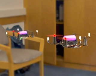
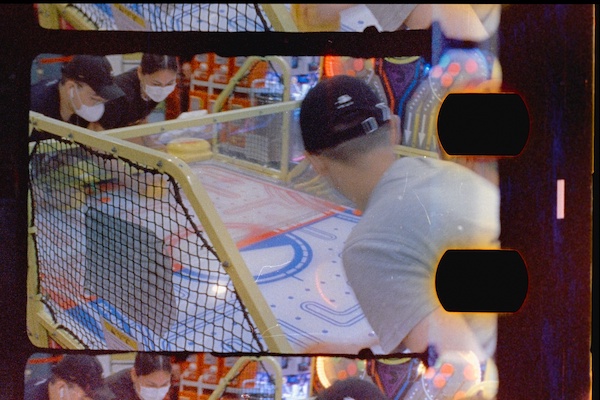
If you haven't noticed from my last few blog posts, I've been pretty obsessed with film stuff recently. In particular, I've been obsessed with the warm & fuzzy look of film videos. Maybe its just my gen z brain being nostalgic of a time before I was born, but film really does just feel special compared to the sterile digital videos of today.
However, there definitely is a reason why no one uses film as a medium for recording videos anymore. Motion picture film is in short supply and it's almost impossible to find someone willing to develop and scan your videos. All in all, you would probably need to wait months and pay ~$250 for just 10 minutes of footage – not exactly the best value proposition!
My Idea
Since motion picture film is so rare and expensive, my idea was to build a film video camera that uses normal photographic film canisters, which are far easier to buy and develop. The only issue is that these film canisters can only take 36 pictures, which equates to a measly 3 seconds of video! Not great.
To try squeeze more footage into these rolls of film, I reduced the image size by a factor of 8, giving us 36*8 = 288 photos per roll. This brings us to about 16 seconds of video per roll of film, at a cost of ~$600 for 10 minutes. That's over 2 times worse than just using a traditional motion picture film camera but I didn't bother to do the math before starting this project and by the time I realised how expensive it was going to be I was already too far in to stop, oops.
The Mechanics
A video is simply a bunch of images shown one after another fast enough to give the illusion of motion. So all we really have to do is take a bunch of photos. Film cameras do this this by intermittently pulling down the film, exposing a single frame at a time. The video below doesn't show it, but we also need to have a shutter to stop light from hitting the film while it's being pulled down, otherwise the image would get all smeared.
Pulldown Mechanism
4 Bar Linkage?
My first idea was to create a 4 bar linkage mechanism to pull the film down.
I kinda went all in with this idea, implementing my own 4 bar linkage simulator in Python using Freudenstein's equation (which is a really cool use of imaginary numbers! Check out this pdf for more details). I then wrote a gradient descent optimiser to find the best 4 bar linkage parameters to follow a given path.
2 Tooth Gear & Cam
But anyway, I ended up scrapping all of work I did with 4 bar linkages so that was a pretty big waste of time. I realised that the mechanism would be far too small and intricate to manufacture using 3D printing, so I instead pivoted to this much more simple pulldown mechanism.
This design is simply a gear with two teeth, which allows it pull the film down once per rotation. There are also two alignment pins which hold the film stationary while an image is being exposed but release when the film is being pulled down.
Unfortunately, this mechanism was plagued with issues. The gear teeth need to be just long enough to grab the film but not so long that it jams. The tolerances here are on the order of 0.1mm, which is really far too much to ask for out of a FDM 3D printer, and is probably what lead to a lot of my reliability issues.
I messed around with the tooth length, spacing and profile for weeks before it started to work semi reliably but I could never get it to work perfectly. There are just too many variables to control, with things such as film stock thickness and film canister friction having a huge impact on performance.
Maybe I'm being a bit too hash on the design though, because after all, it did end up producing some pretty good results. But if I were to do it again, the pulldown design would be the first thing I would change.
Shutter
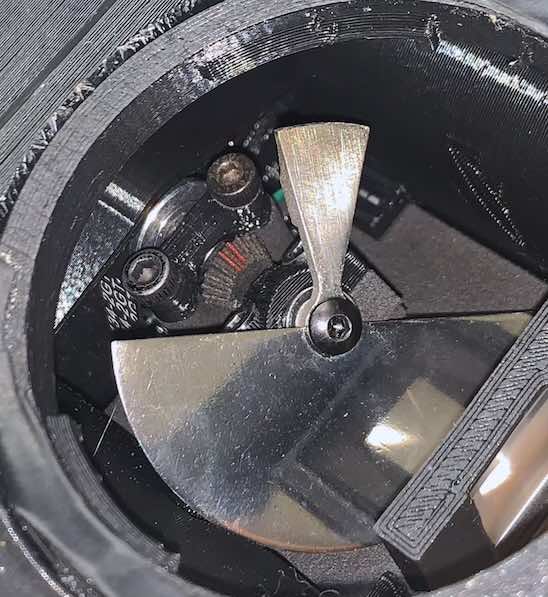
For my camera, I chose a pretty typical 150 degree shutter (this means that the film is exposed 150°/360° = 41% of the time). As mentioned above, the shutter has to block light from hitting the film while it is being pulled down to prevent image smearing, so the shutter has to be mechanically linked to the pulldown mechanism. This is done through a few gt2 belts and a 45 degree gear.
The shutter itself is 3D printed stainless steel because it needs to be shiny (see "Viewfinder" section below for explanation). The shutter also has a counterweight on one side to balance it, because an unbalanced shutter rotating at 1000rpm would shake the camera around and blur the image. On a side note, it's kinda incredible how cheap metal 3D printing is now-days. This metal part cost only $10 including shipping and was at my door just one week after I ordered it.
Viewfinder
One of my aims for the camera was for it to have a through-the-lens (TTL) viewfinder, which means that you are seeing exactly what is being recorded. This was primarily because TTL cameras allow you to see if your video is in focus or not (rather important).
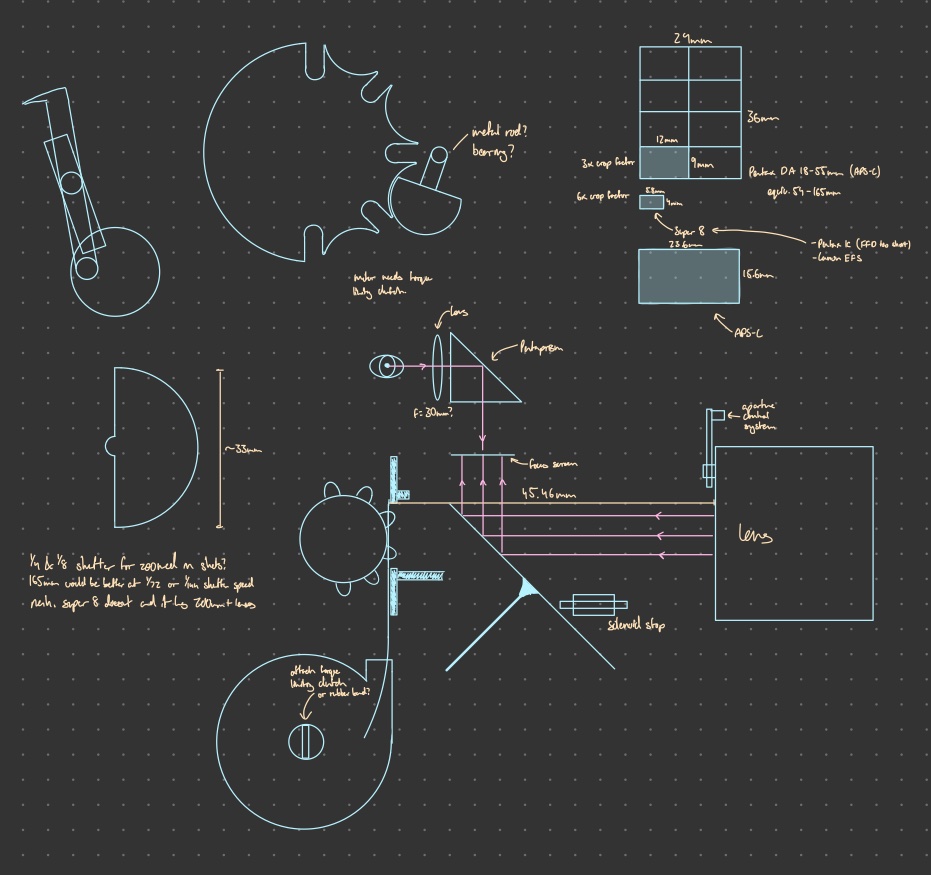
There are two ways of doing this:
The first is to use a beam splitter prism, which sends half of the light to the film and the other half to the viewfinder. This is what super8 and consumer super16 camera's do, because of its mechanical simplicity. However, the downside is that you lose a half of the light and the prism can degrade the image quality.
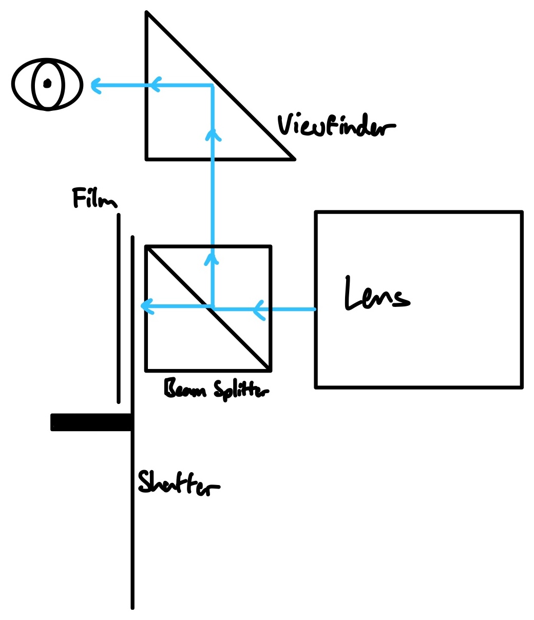
The other option is to angle the shutter 45°, so that when the shutter is blocking the film it's redirecting the light to the viewfinder. This means that no light is lost and the image quality isn't degraded.
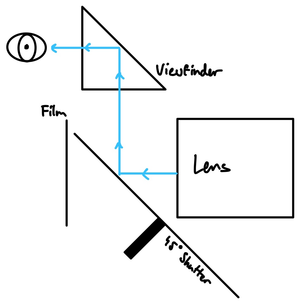
The image is then sent into a pentaprism, which flips the image horizontally (so it's the correct orientation) and puts the image into your eye. For this, I used a replacement viewfinder part for Canon 1000D which I bought on Aliexpress. Honestly, getting a viewfinder from a spare parts shop was one of my smartest moves, trying to assemble my own viewfinder with lenses and a pentaprism would have been a nightmare.
Anyway, for the light redirection I chose the second option of a 45° shutter. However, this method ended up being far more difficult than I initially thought. Here are a few of the issues I faced:
- The shutter needs to be angled at 45° but it's really hard to find 45° bevel gears online. I ended up having to design and order 3D printed nylon gears.
- Physically, there is almost no space to fit a 45° shutter between the film plane and lens. It's a seriously tight fit. I don't know how professional 35mm film movie cameras manage to effortlessly fit the shutter into the camera.
- The shutter needs to be completely flat and have a mirror finish. After hours of sanding and polishing I got pretty close, but the image in the viewfinder is still kinda blurry.
- It is extremely hard to adjust the shutter's position, which means the focus you see through the viewfinder can't be calibrated to be the same as what is being recorded. Kinda defeats the whole purpose of a TTL camera 🤦♂️.
So yeah, it wasn't exactly a smooth process.
Lens
I used the Canon EFS 18-55mm lens for this camera, simply because it was the cheapest lens I could find online. Like most things with my camera, this ended up being a terrible idea! The lens has no focus scale, and since the viewfinder was not able to help me focus, a focus scale was the only way I could pull focus. This meant I had to draw my own very janky focus scale on the lens. It looks sketchy but then again my whole camera looks sketchy.
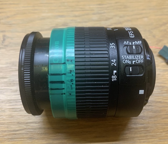
Even more annoyingly, this lens isn't parfocal, or even close to it. A parfocal lens means that its focus won't change as you zoom in and out. So since my lens wasn't parfocal, if you change the zoom of the lens mid shot the scene will go out of focus! This can be remedied by simply stopping down the lens to around f/11 (a smaller aperture increases the depth of field enough that the non-parfocal nature of the lens isn't noticeable, especially with low res film).
Lastly, the lens lets in less light when you zoom in which means the image exposure changes as you change the zoom. So yeah, maybe buying a $40 lens was a bad idea.
To summarise, don't be stupid like me! Get a lens that:
- Has a focus scale
- Is parfocal (or close to it)
- Doesn't change exposure when zooming
Electronics & Programming
Microcontroller
I chose to use the an ESP32 microcontroller with an integrated LCD screen for this project. The ESP32 has quickly become one of my favourite microcontroller; it only costs a few dollars, has plenty of power and even has two cores for running code in parallel!
The Lens (again)
Yeah this stupid lens caused me even more problems. The only way to change the aperture is through the electronic interface connecting the lens and the camera, however the Canon lens communication protocol is completely closed sourced. This is rather annoying – changing the aperture is like 1/3 of a lens' job!
There are almost no resources online about the Canon lens protocol. I spent hours searching the internet but only found janky, half working protocol specifications. However, eventually I stumbled across the holy grail of Canon lens protocol documentation: this 100 page pdf written by jp79dsfr.free.fr. Nothing even comes close to the level of detail in this pdf, the author must have spent 100's of hours painstakingly reverse engineering the protocol's instructions.
However there's one issue – it's all in French.
So I sent the pdf through Google translate and read over all 100 pages of poorly translated documentation. There is also a companion document with some code examples which is another extremely useful resource, however all the code is written across pages of a pdf which is probably the worst way to share code lol.
With these resources, I was able to write my own implementation of the Canon lens protocol in C++ to control the aperture and active image stabilisation of the lens. You can check out the code on the GitHub repo
I can't thank the author enough for dedicating so much time into such an absurdly niche topic. I absolutely love the blurb at the top of the their website. It says (in French):
You who enter here, lose all hope.
Welcome to technical hell ... no photo or wallpaper will be found in these places, even the artistic aspect of the shooting will not be or almost not addressed.
This guy is on the exact same wavelength as me, appreciating the technical side of photography far more than the actual composition techniques or artistry.
Film Jam Sensor
A cool feature on this camera is that it has an optical sensor to detect if the film has jammed. I used a little opto-interrupter sensor to count how many sprocket holes have passed by. This can then be used to automatically stop the motor if the sensor detects that the film has stopped moving through the camera properly.
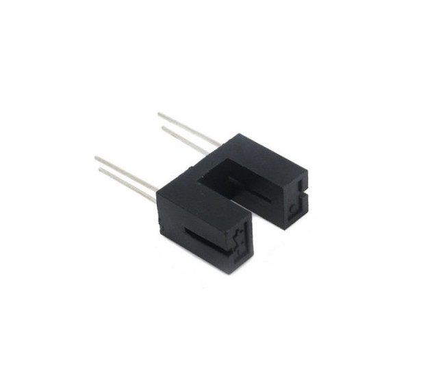
Now you're probably like "wait an opto-interrupter literally uses light, won't that ruin the film?" but the sensor works in the infrared range, which colour film isn't sensitive to. This might be a problem if you use Aerochrome (an infrared sensitive film) in the camera but like why on earth would you put an ultra rare $300 roll of film through this incredibly unreliable camera??? (btw you should absolutely check out my blog post on recreating Aerochrome)
Controlling the motor
I used a Nema 17 stepper motor to drive the camera along with a A4489 stepper driver. I cranked the stepper driver current up to its maximum setting, since the motor only runs for 10 seconds at a time.
Anyway I somehow managed to blow up like 10 of these stepper drivers throughout the project. I couldn't figure out why they kept exploding but they're so cheap that it was easier to just buy a ton and keep replacing them than to try debug why they kept breaking.
The motor speed is limited by the speed that the microcontroller can send step pulses to the stepper motor driver. Since I check the opto-interrupter sensor every step, the max speed the camera can shoot is only around 24fps. I could definitely improve this by utilising both of the ESP32's cores, but the camera pulldown mechanism barely works properly at 18fps let alone 24fps.
Creating the Video
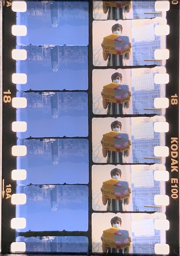
Converting Analog Film to Digital Images
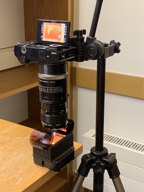
If everything has gone properly, the developed film should contain a couple hundred thumbnail sized images. Now we have to do the most tedious step: digitally scanning all of these photos
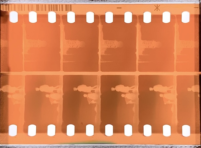
To do this, I placed the film on top of a strong backlight and used a macro lens to take photos of the film with my digital camera. This is essentially a DSLR scanning setup, which is quite common in the film photography world. The images are far smaller than normal 35mm frames however, which means you need to use a macro lens with a very high magnification factor and a camera with a small sensor size. Make sure to also set the camera exposure to manual so it isn't changing from photo to photo.
Here's the gear I used
- Camera: Sony a6000
- Lens: Canon FD 50mm Macro w/ 50mm extension tube
- Backlight: This cheap thing that I found on Aliexpress
- Negative holder: 3D printed (file in GitHub)
Ironically, I had to buy my first ever digital camera for this project!
Anyway this process is pretty tedious as you can imagine. Each roll of film has ~280 images which takes about 30 minutes to scan. I could have built a machine to automatically scan the film but I just wasn't scanning enough film to justify it.
Negative Inversion
Film negatives are, as the name implies, negatives of the actual image. There are some expensive "slide film" stocks which show positive images, but we'll ignore that for now.
Inverting a film negative is more of an art than a science, and as someone who is far better at science than art this was a bit of an issue. Like most image based problems, I tried throwing OpenCV at it but I could never get the inverted colours to look correct.
I ended up caving in and going with the gold standard for negative inversion: Negative Lab Pro (NLP). Unfortunately, this is quite an expensive route. NLP is a one time purchase of $100 and it also requires Lightroom which is about $10 per month. The results from NLP are undeniably great though, and Lightroom is also an incredibly useful tool when you're working with 1000s of images so the investment is worth it in my opinion.
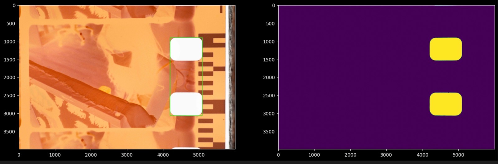
Machine Vision Image Alignment
Since we manually took all these photos, the frames are all going to be misaligned. If we were to simply string the images into a video it would be a jumpy mess. Therefore, we need to align the images so the sprocket holes are always in the same place.
I wrote a little OpenCV Python script to do this. The code is in the GitHub repo, and it explains how to run the program. The code quality is pretty horrific (I threw it together in an afternoon), but it works!
Stitching Frames Together
At this point, you should have a folder containing all the inverted and aligned images. Now all we need to do is string the images together into a video! You could put the ~150 images into a powerpoint and flip through it really fast but here's an easier method that uses FFmpeg.
-
Run this command in the folder with all the images
ffmpeg -framerate 18 -pattern_type glob -i '*.jpg' -c:v libx264 -pix_fmt yuv420p out.mp4 -
This may not be necessary for you, but I needed to use handbrake to re-encode
out.mp4because my Mac refuses to read the .mp4 file outputted by FFmpeg
You can also use FFmpeg to stabilise the video
-
Crop out the film border
ffmpeg -i out.mp4 -filter:v "crop=in_w/2:in_h/2:in_w/8:in_h/4" -c:a copy out_crop.mp4 -
Calculate stabilisation data based on cropped file
ffmpeg -i out_crop.mp4 -vf vidstabdetect=stepsize=32:shakiness=10:accuracy=15:result=transforms.trf -f null - -
Apply the stabilisation data to the un-cropped file
ffmpeg -i out.mp4 -y -vf vidstabtransform=input=transforms.trf:maxangle=0:smoothing=4:optzoom=0 -vcodec libx264 -tune film -an stabilized.mp4
And now you should be left with a finished video! Not exactly a simple workflow but it works.
Conclusion
This was definitely one of my biggest projects yet. I spent 4 months and hundreds of dollars on film and parts, so I'm extremely happy that I was able to get such great results in the end.
This film camera project combined all of my interests: CAD modelling, 3D printing, embedded programming, film photography, camera design, machine vision and so much more. It's honestly pretty incredible how well this project aligned with my rather random skillset. At every phase of the project I was working on something new which is honestly the only reason I was able to work on it for 4 months straight.
So so so many failures
This camera was far from perfect. Actually it was pretty shit. Over the course of the summer it probably only worked about half of the time. I would always end up lugging this huge bomb looking contraption to beach days, hikes and parties only for it to not work when I got there. It would always be some stupid issue, like a motor driver dying or wire snapping, but there were so many moving parts and absolutely no redundancy so even the smallest failure would render the entire camera useless.
These failures were so frequent that I ended up bringing along a mini workshop with me whenever I was planning on using the camera, which honestly was ridiculous but I was really desperate to get some footage at that point.
Improvements
Excluding the stupid failures, the most common issue was the film not being pulled down properly. Either the images weren't aligned with the sprocket holes causing a jumpy video or the film didn't get pulled down at all. As I mentioned in the "Pulldown Mechanism" section, the design had such stupidly tight tolerances that even the difference in thickness between film stocks could throw it off. If I were to make another camera, I would definitely use a different design.
Also, as I mentioned in the "Viewfinder" section, I wouldn't use a 45° shutter again. It would have been so much easier to just use a shutter parallel with the film plane and a splitting prism to get light to the viewfinder. The 1 stop loss of light honestly isn't even that bad, and it would allow me to focus accurately through the viewfinder and also just make the overall design of the camera much simpler.
I also regret cheaping out on my lens. I should have gotten a lens which was parfocal, didn't change exposure when zooming and had a focus scale – it would have made the camera a lot more usable.
So what's next
As much as it saddens me, I really don't see myself using this camera again. Perhaps I'll use it to film some clips with me and my friends in my dorm or something like that, but I would never bring it with me on a holiday like I once envisioned. It sounds kinda stupid, but using this camera was just unbearably stressful. There were so many times over the summer where I was out doing something fun with my friends or family, but all I could think about was whether my film camera would work or not. I don't wan't that extra bit of stress hanging over me whenever I'm supposed to having fun, it simply isn't worth it.
I still do love the look of film videos however, and I'll probably buy myself a small super 8 camera to bring with me on trips. I had previously avoided super 8 because I thought that it was ludicrously expensive, but at ~$40 per minute it's literally half the price of using my camera lol.
I absolutely don't regret building the camera though. Some of my favourite memories from last summer were captured by it, and the fact that they were painstakingly shot on my fragile film camera makes them even more special.